Electronic circuits > Lights & L.E.Ds > Alternating Flasher
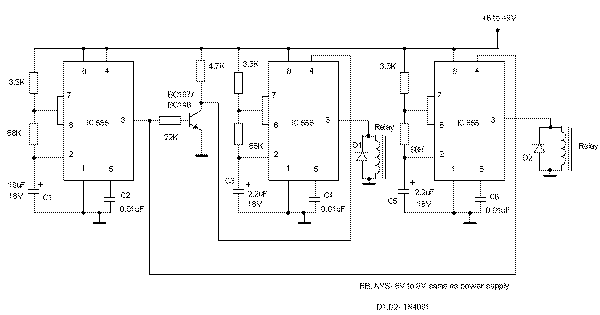
Alternating Flasher This circuit uses three easily available 555 timer ICs. All three work as
astable multivibrators. The first 555 has an on period and off period equal to 1
sec. This IC controls the on/ off periods of the other 2 555s which are used to
flash two bulbs through the relay contacts.
The flashing occurs at a rate of 4 flashes per second.
The diodes are used to protect the 555 ICs from peaks. The relays should have an
impedance greater than 50ohms i.e, they should not draw a current more than
200mA.
The flashing sequence is as follows:
The bulb(s) connected to the first relay flashes for about 1 sec at a rate of 4
flashes per second. Then the bulb(s) connected to the second relay flashes for 1
sec at a rate of 4 flashes per second. Then the cycle repeats.
The flashing rates can be varied by changing the capacitors C3 and C5. A higher
value gives a lower flashing rate.
Note that the values of C3 and C5 should be equal and should be less than that
of C1.
The value of C1 controls the change-over rate ( default 1sec). A higher value
gives a lower change-over rate.
If you use the normally open contacts of the relay, on bulb will be OFF while
other is flashing,and vice versa.
If normally closed contacts are used, one bulb will be ON while the other is
flashing.
Published on: 2004-08-21 (3290 reads)
[ Back | Home ] | 
